Executive Summary (Introduction-CEV): NASA Exploration Systems Architecture Study Final Report (DRAFT) October 2005
1. Executive Summary
1.1 Introduction
1.4 Crew Exploration Vehicle (CEV)
1.4.1 Overview
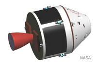
One of the key requirements to enable a successful human space exploration program is the development and implementation of a vehicle capable of transporting and housing crew on LEO, lunar, and Mars missions. A major portion of the ESAS effort focused on the design and development of the CEV, the means by which NASA plans to accomplish these mission objectives. The CEV reference design includes a pressurized CM to support the Earth launch and return of a crew of up to six, a Launch Abort System (LAS), and an unpressurized SM to provide propulsion, power, and other supporting capabilities to meet the CEV’s in-space mission needs.
In response to the ESAS charter, the first crewed flight of the CEV system to the ISS was assumed to occur in 2011. The CEV design requirements were, however, to be focused on exploration needs beyond LEO. Therefore, the requirements team started with the existing ESMD Rev. E Crew Transportation System (CTS) requirements and assessed these against ISS needs for areas of concern where CEV may fall short of ISS expectations. Any such shortcomings were then examined on a case-by-case basis to determine whether they were critical to performing the ISS support function. If they were found not to be critical, such shortcomings were considered as guidelines and not requirements on the CEV.
While the CEV design was sized for lunar missions carrying a crew of four, the vehicle was designed to also be reconfigurable to accommodate up to six crew for ISS and future Mars mission scenarios. The CEV can transfer and return crew and cargo to the ISS and stay for 6 months in a quiescent state for emergency crew return. The lunar CEV design has direct applications to ISS missions without significant changes in the vehicle design. The lunar and ISS configurations share the same SM, but the ISS mission has much lower Delta-V requirements. Hence, the SM propellant tanks can be loaded with additional propellant for ISS missions to provide benefits in launch aborts, on-orbit phasing, and ISS re-boost. Other vehicle block derivatives can deliver pressurized and unpressurized cargo to the ISS.
Vehicle size, layout, and mass were of central importance in this study, as each factors into vital aspects of mission planning considerations. Detailed subsystem definitions were developed and vehicle layouts were completed for a four-crew lunar DRM and a six-crew Mars DRM. The lunar mission was a design driver since it had the most active days with the crew inside. The Mars DRM, which was a short duration mission of only 1 to 2 days to and from an orbiting MTV, drove the design to accommodate a crew of six. Ultimately, the CEV CM was sized to be configurable for accommodating six crew members even for an early mission to the ISS.
Additional details on the CEV trade studies and analysis results are contained in Section 5 of this report.
1.4.2 CEV Modular Design Approach
The different CEV vehicle configurations were each assigned a block number to distinguish their unique functionality. The Block 1 vehicles support the ISS with transfer of crew and cargo. The Block 1A vehicle transfers crew to and from the ISS. This vehicle can stay at the ISS for 6 months. Varying complements of crew and pressurized cargo can be transported in the Block 1A CM. The Block 1B CM transports pressurized cargo to and from the ISS. The crew accommodations are removed and replaced with secondary structure to support the cargo complement. The relationship between the Block 1A and Block 1B CMs is similar to that of the Russian Soyuz and Progress vehicles. Unpressurized cargo can be transported to the ISS via the CDV. The CDV replaces the CM with a structural “strong back” that supports the cargo being transferred. The CDV uses the same SM as the other blocks and also requires a suite of avionics to perform this mission. The CDV is expended after its delivery mission. The Block 2 CEV is the reference platform sized to transfer crew to the lunar vicinity and back. Detailed sizing was performed for this configuration and the other blocks were derived from its design. The Block 3 configuration is envisioned as a crewed transfer vehicle to and from an MTV in Earth orbit. The crew complement for this configuration is six. No detailed design requirements were established for this block and detailed mass estimates were never derived.
Design details for each block configuration are discussed in Section 5 of this report. A mass summary for each block is shown in Figure 1-17. Detailed mass statements were derived for each block and are provided in Appendix 5A.

1.4.2.1 Block 2 Lunar CEV
The lunar CEV CM, in conjunction with the SM and LV/EDS, is used to transport four crew members from Earth to lunar orbit and return them to Earth. The CM provides habitable volume for the crew, life support, docking and pressurized crew transfer to the LSAM, and atmospheric entry and landing capabilities. Upon return, a combination of parachutes and airbags provide for a nominal land touchdown with water flotation systems included for water landings following an aborted mission. Three main parachutes slow the CEV CM to a steady-state sink rate of 7.3 m/s (24 ft/s), and, prior to touchdown, the ablative aft heat shield is jettisoned and four Kevlar airbags are deployed for soft landing. After recovery, the CEV is refurbished and reflown with a lifetime up to 10 missions.
A scaled Apollo Command Module shape with a base diameter of 5.5 m and sidewall angle of 32.5 degrees was selected for the outer moldline (OML) of the CEV CM. This configuration provides 29.4 m3 of pressurized volume and 12 to 15 m3 of habitable volume for the crew during transits between Earth and the Moon. The CEV CM operates at a nominal internal pressure of 65.5 kPa (9.5 psia) with 30 percent oxygen composition for lunar missions, although the pressure vessel structure is designed for a maximum pressure of 101.3 kPa (14.7 psia). Operating at this higher pressure allows the CEV to transport crew to the ISS without the use of an intermediate airlock. For the lunar missions, the CM launches with a sea-level atmospheric pressure (101.3 kPa), and the cabin is depressurized to 65.5 kPa prior to docking with the LSAM.
The lunar CEV CM propulsion system provides vehicle attitude control for atmospheric entry following separation from the SM and range error corrections during the exoatmospheric portion of a lunar skip-entry return trajectory. A gaseous oxygen/ethanol bipropellant system is assumed with a total Delta-V of 50 m/s.
Illustrations of the reference Lunar CEV CM are shown in Figure 1-18.

1.4.2.2 Block 2 Lunar CEV SM
The lunar CEV SM is included in the ESAS exploration architecture to provide major translational maneuvering capability, power generation, and heat rejection for the CEV CM. The SM assumes an integrated pressure-fed oxygen/methane OMS and RCS system to perform rendezvous and docking with the LSAM in Earth orbit, any contingency plane changes needed prior to lunar ascent, TEI, and self-disposal following separation from the CM. One 66.7-kN (15,000-lbf) OMS engine and twenty-four 445-N (100-lbf) RCS thrusters, engines common to both the SM and the LSAM ascent stage, are used for on-orbit maneuvering. The SM propellant tanks are sized to perform up to 1,724 m/s of OMS and 50 m/s of RCS Delta-V with the CEV CM attached and 15 m/s of RCS Delta-V after separation. In the event of a late ascent abort off the CLV, the SM OMS engines may also be used for separating from the LV and either aborting to near-coastline water landings or aborting to orbit.
Two deployable, single-axis gimbaling solar arrays are also included to generate the necessary CEV power from Earth-Orbit Insertion (EOI) to CM-SM separation prior to entry. For long-duration outpost missions to the lunar surface, lasting up to 180 days, the CEV remains unoccupied in lunar orbit. Solar arrays were selected instead of fuel cells or other similar power generation options because the reactant mass requirements associated with providing keep-alive power during the long dormant period for fuel cells became significantly higher than the mass of a nonconsumable system such as solar arrays. The solar arrays use state-ofthe- art three-junction photovoltaic cells. Finally, the SM composite primary structure also provides a mounting location for four radiator panels. These panels provide heat rejection capability for the CEV fluid loop heat acquisition system.
Illustrations of the reference lunar CEV SM are shown in Figure 1-19.

1.4.2.3 Block 2 Launch Abort System (LAS)
The LAS was sized to pull the CEV CM away from a thrusting LV at 10 g’s acceleration. The LAS sizing concept is similar to the Apollo Launch Escape System (LES) in that it is a tractor system that is mounted ahead of the CM. The main difference is that the exhaust nozzles are located near the top of the motor which will reduce the impingement loads on the CM. The LAS features an active trajectory control system based on solid propellant, a solid rocket escape motor, forward recessed exhaust nozzles, and a CM adaptor. The motor measures 76 cm in diameter and 5.5 m in length, while eight canted thrusters aid in eliminating plume impingement on the CM. A star fuel grain minimizes motor size and redundant igniters are intended to guarantee the system’s start.
The LAS provides abort from the launch pad and throughout powered flight of the booster first stage. The LAS is jettisoned approximately 20 to 30 seconds after second stage ignition. Further analyses are required to determine the optimum point in the trajectory for LAS jettison. After the LAS is jettisoned, launch aborts for the crew are provided by the SM propulsion system.
The mass for a 10-g LAS for a 21.4 mT CM is 4.2 mT. Figure 1-20 depicts the LAS on top of the CM.

1.4.2.4 Block 1A ISS CEV CM and SM
The ISS CEV CM in the ESAS architecture is the Block 1 variant of the lunar CM designed to rotate three to six crew members and cargo to the ISS. The ISS CM is designed largely to support lunar exploration requirements, with a minimal set of modifications made to support ISS crew rotation. Initial mass for the three-crew ISS CM variant is 162 kg less than the lunar CM mass, with the assumed system modifications listed below:
- Removed EVA support equipment for one crew member (-3 kg);
- Sized galley, waste collection consumables, and soft stowage for 18 crew-days instead of 53 crew-days (-19 kg);
- Removed one crew member and sized personnel provisions for 18 crew-days (-238 kg);
- Added ISS cargo (+400 kg);
- Sized oxygen, nitrogen, and potable water for 18 crew-days (-156 kg);
- Sized RCS propellant for smaller vehicle mass and lower Delta-V (-145 kg); and
- Less growth allocation for lower vehicle dry mass (-4 kg).
The ISS SM is identical to the SM designed for lunar exploration, except that propellant is off-loaded to reflect the lower Delta-V requirements of ISS crew rotation compared to LOR. Propellant requirements for the ISS SM are estimated based on using the largest vehicle the SM may deliver to the ISS and subsequently deorbit, which is currently the unpressurized CDV. Other potential ISS payloads for the SM are the crewed CEV CM and pressurized cargo CEV; however, these have total masses less than the unpressurized CDV. The CDV has a total mass of 12,200 kg, compared to 9,342 kg for the three-crew CEV, 9,551 kg for the six-crew CEV, and 11,381 kg for the pressurized cargo delivery CEV.
1.4.2.5 Block 1B ISS Pressurized Cargo CM Variant
The ESAS architecture also includes a variant of the ISS CEV CM that may be used to deliver several tons of pressurized cargo to the ISS without crew on board and return an equivalent mass of cargo to a safe Earth landing. This spacecraft is nearly identical to the ISS crew rotation variant, with the exception that the personnel and most components associated with providing crew accommodations are removed and replaced with cargo. Initial mass for the uncrewed ISS CM variant is 2,039 kg greater than the three-crew ISS crew rotation CM, with the assumed system modifications listed below:
- Removed atmosphere contaminant (Carbon Dioxide (CO2), etc.) control equipment (-165 kg);
- Removed EVA support equipment (-21 kg);
- Removed galley, waste collection system, and cargo transfer bags (-84 kg);
- Removed mass for personnel and personnel provisions (-580 kg);
- Removed 500 kg of ISS cargo and ballast, and added 3,500 kg of ISS cargo (+3,000 kg);
- Loaded oxygen, nitrogen, and water as needed for the pressurized cargo mission (-64 kg);
- Increased RCS propellant for higher vehicle mass (+8 kg); and
- Less growth allocation for lower vehicle dry mass (-54 kg).
1.4.2.6 ISS Unpressurized Cargo Delivery Vehicle (CDV)
The ISS CDV was sized to deliver unpressurized cargo to the ISS. The CDV is mainly a structural “strong-back” with a CBM for attachment to the ISS. The CDV utilizes the same SM as the other block configurations for transfer from the LV injection orbit to the ISS. Because the avionics for the other CEV variants are located within the CM, an avionics pallet is required for the CDV. This pallet would support the avionics and provide the connection to the ATCS on the SM.
The CDV was sized to transport two 1,500-kg unpressurized ORUs for the ISS. Examples of ORUs include Control Moment Gyroscopes (CMGs) and pump packages. The packaging factor for these ORUs was assumed to be 100 percent; therefore, the trays and secondary support structure for the cargo is estimated to be 3,000 kg, for a total cargo complement of 6,000 kg. The total estimate for the CDV without the SM is 12,200 kg.
Operationally, the CDV would perform automated rendezvous and proximity operations with the ISS and would then be grappled by the SSRMS and berthed to an available port. Two releasable cargo pallets are used to provide structural attachment for the ORUs. The cargo pallets can be grappled by the SSRMS and relocated to the ISS truss as required. Once the cargo has been relocated on the ISS, the CDV would depart from the ISS and perform an automated deorbit burn for burnup and disposal in the ocean.
Illustrations of the reference CDV are shown in Figures 1-21 and 1-22.

The ESAS reference Mars mission utilizes a Block 3 CEV to transfer a crew of six between Earth and an MTV at the beginning and end of the Mars exploration mission. A Block 3 CEV CM and SM is launched by the CLV into an orbit matching the inclination of the awaiting MTV. The CEV is first injected into a 55×296-km altitude orbit while the MTV loiters in a circular orbit of 800- to 1,200-km altitude. It then takes the CEV up to 2 days to perform orbit-raising maneuvers to close on the MTV, conducting a standard ISS-type rendezvous and docking approach to the MTV. After docking, the CEV crew performs a leak check, equalizes pressure with the MTV, and opens hatches. Once crew and cargo transfer activities are complete, the CEV is configured to a quiescent state and remains docked to the MTV for the trip to Mars and back. Periodic systems health checks and monitoring is performed by the ground and flight crew throughout the mission.
As the MTV approaches Earth upon completion of the 1.5- to 2.5-year round-trip mission, the crew performs a pre-undock health check of all entry critical systems, transfers to the CEV, closes hatches, performs leak checks, and undocks from the MTV. The CEV departs 24 to 48 hours prior to Earth entry, and the MTV then either performs a diversion maneuver to fly by Earth or recaptures into Earth orbit. After undocking, the CEV conducts an onboard-targeted, ground-validated burn to target for the proper entry corridor, and, as entry approaches, the CEV CM maneuvers to the proper Entry Interface (EI) attitude for a direct-guided entry to the landing site. Earth entry speeds from a nominal Mars return trajectory may be as high as 14 km/s, compared to 11 km/s for the Block 2 CEV. The CEV performs a nominal landing at the primary land-based landing site and the crew and vehicle are recovered.
Figure 1-23 shows the Block 3 CEV CM configured to carry six crew members to the MTV.

1.4.3 CEV Design Evolution
The design and shape of the CEV CM evolved in four design cycles throughout the study, beginning with an Apollo derivative configuration 5 m in diameter and a sidewall angle of 30 degrees. This configuration provided an OML volume of 36.5 m3 and a pressurized volume of 22.3 m3. The CM also included 5 g/cm2 of supplemental radiation protection on the cabin walls for the crew’s protection. Layouts for a crew of six and the associated equipment and stowage were very constrained and left very little habitable volume for the crew. It was determined that the internal volume for the CM was too small, especially for a surface direct mission where the CEV would be taken to the lunar surface.
A larger CEV was considered in Cycle 2 which grew the outer diameter to 5.5 m and reduced the sidewall angles to 25 degrees. Both of these changes substantially increased the internal volume. The pressurized volume increased by 75 percent to 39.0 m3 and the net habitable volume increased by over 50 percent to 19.4 m3. The desire in this design cycle was to provide enough interior volume for the crew to be able to stand up in and don/doff lunar EVA suits for the surface direct mission. Most of the system design parameters stayed the same for this cycle including the 5 g/cm2 of supplemental radiation protection.
Cycle 3 reduced the sidewall angles even further to 20 degrees in an effort to achieve monostability on Earth entry. The sidewall angle increased the volume further. Because the increases in volume were also increasing the vehicle mass, the height of the vehicle was reduced by 17 inches, reducing the height-to-width aspect ratio. This configuration showed the most promise in the quest for monostability, but the proper center of gravity was still not achieved. Analysis in this design cycle showed that the supplemental radiation protection could be reduced to 2 g/ cm2. Figure 1-24 illustrates the progression of the configurations through Cycle 3 of the study as compared to Apollo and the attached table details the changes in diameter, sidewall angle, and volume. Data for Cycle 4 is also shown and is described in the following paragraphs.
Cycle 4 was the final CEV design cycle and began after the decision was made to no longer consider the lunar surface direct mission. The design implications to the CEV and the low mass margins surrounding the lunar surface direct mission mode were the primary reasons for taking the mode out of consideration. A lunar surface direct CEV has very little commonality to a CEV servicing the ISS, especially in regards to the SM because of substantially different Delta-Vs. The Cycle 4 CEV was sized for a two-launch EOR-LOR mission mode where the CEV performs a rendezvous with the EDS and LSAM in LEO, stays in lunar orbit while the LSAM descends to the lunar surface, and performs another rendezvous with the LSAM in lunar orbit. No supplemental radiation protection was included in the mass estimates for this design analysis due to results from a radiation study reported in Section 4 of this report.

The resulting Cycle 4 CM shape is a photographic scaling of the Apollo Command Module. The vehicle is 5.5 m in diameter and the CM has a sidewall angle of 32.5 degrees. The resulting CM pressurized volume is approximately 25 percent less than the Cycle 3 volume, but has almost three times the internal volume as compared to the Apollo Command Module. The CEV was ultimately designed for the EOR-LOR “1.5-launch solution” and volume reduction helps to reduce mass to that required for the mission. Figure 1-25 depicts how vehicle sidewall angle and diameter affect pressurized volume and the resulting design point for each cycle.

1.4.4 Recommendations
It is recommended that the CEV incorporate a separate CM, SM, and LAS arrangement similar to that of Apollo, and that these modules be capable of multiple functions to save costs. The CEV design was sized for lunar missions carrying a crew of four. Also, the vehicle was designed to be reconfigurable to accommodate up to six crew for ISS and future Mars mission scenarios. The CEV can transfer and return crew and cargo to the ISS and stay for 6 months in a quiescent state for emergency crew return. The lunar CEV design has direct applications to ISS missions without significant changes in the vehicle design. The lunar and ISS configurations share the same SM, but the ISS mission has much lower Delta-V requirements. Hence, the SM propellant tanks can be loaded with additional propellant for ISS missions to provide benefits in launch aborts, on-orbit phasing, and ISS reboost. Other vehicle block derivatives can deliver pressurized and unpressurized cargo to the ISS.
The ESAS CEV team’s next recommendation addresses the vehicle shape. Using an improved blunt-body capsule for the CM was found to be the least costly, fastest, and safest approach for bringing ISS and lunar missions to reality. The key benefits for a blunt-body configuration were found to be lower weight, a more familiar aerodynamic design from human and robotic heritage (resulting in less design time and cost), acceptable ascent and entry ballistic abort load levels, crew seating orientation ideal for all loading events, and easier LV integration and entry controllability during off-nominal conditions. Improvements on the Apollo shape will offer better operational attributes, especially by increasing the Lift-to-Drag (L/D) ratio, improving Center of Gravity (CG) placement, potentially creating a monostable configuration, and employing a lower angle of attack for reduced sidewall heating.
A CM measuring 5.5 m in diameter was chosen to support the layout of six crew without stacking the crewmembers above or below each other. A crew tasking analysis also confirmed the feasibility of the selected vehicle volume. The recommended pressurized volume for the CM is approximately three times that of the Apollo command module. The available internal volume provides flexibility for future missions without the need for developing an expendable mission module. The vehicle scaling also considered the performance of the proposed CLV, which is a four-segment SRB with a single SSME upper stage. The CEV was scaled to maximize vehicle size while maintaining adequate performance margins on the CLV.
It is recommended that the CEV utilize an androgynous Low-Impact Docking System (LIDS) to mate with other exploration elements and to the ISS. This requires the CEV-to-ISS docking adapters to be LIDS-compatible. It is proposed that two new docking adapters replace the Pressurized Mating Adapter (PMA) and Androgynous Peripheral Attachment System (APAS) adapters on the ISS after Shuttle retirement.
An integrated pressure-fed LOX and methane OMS/RCS propulsion system is recommended for the SM. Selection of this propellant combination was based on performance and commonality with the ascent propulsion system on the LSAM. The risk associated with this type of propulsion for a lunar mission can be substantially reduced by developing the system early and flying it to the ISS. There is high risk in developing a LOX/methane propulsion system by 2011, but development schedules for this type of propulsion system have been studied and are in the range of hypergolic systems.
Studies were performed on the levels of radiation protection required for the CEV CM. Based on an aluminum cabin surrounded by bulk insulation and composite skin panels with a Thermal Protection System (TPS), no supplemental radiation protection is recommended. Solar arrays combined with rechargeable batteries were recommended for the SM due to the long mission durations dictated by some of the DRMs. The ISS crew transfer mission and long-stay lunar outpost mission require the CEV to be on orbit for 6 to 9 months, which is problematic for fuel cell reactants.
The choice of a primary land landing mode was primarily driven by a desire for land landing in the continental United States (CONUS) for ease and minimal cost of recovery, post-landing safety, and reusability of the spacecraft. However, it is recommended that the design of the CEV CM should incorporate both a water- and land-landing capability. Ascent aborts will require the ability to land in water, while other off-nominal conditions could lead the spacecraft to a land landing, even if not the primary intended mode. However, a vehicle designed for a primary land-landing mode can more easily be made into a primary water lander than the reverse situation. For these reasons, the study attempted to create a CONUS land-landing design from the outset, with the intention that a primary water lander would be a design offramp if the risk or development cost became too high.
In order for CEV entry trajectories from LEO and lunar return to use the same landing sites, it is recommended that NASA utilize skip-entry guidance on the lunar return trajectories. The skip-entry lunar return technique provides an approach for returning crew to a single CONUS landing site anytime during a lunar month. The Apollo-style direct-entry technique requires water or land recovery over a wide range of latitudes. The skip-entry includes an exoatmospheric correction maneuver at the apogee of the skip maneuver to remove dispersions accumulated during the skip maneuver. The flight profile is also standardized for all lunar return entry flights. Standardizing the entry flights permits targeting the same range-to landing site trajectory for all return scenarios so that the crew and vehicle experience the same heating and loads during each flight. This does not include SM disposal considerations, which must be assessed on a case-by-case basis.
For emergencies, it is recommended that the CEV also include an LAS that will pull the CM away from the LV on the pad or during ascent. The LAS concept utilizes a 10-g tractor rocket attached to the front of the CM. The LAS is jettisoned from the launch stack shortly after second stage ignition. Launch aborts after LAS jettison are performed by using the SM propulsion system. Launch abort study results indicate a fairly robust abort capability for the CEV/CLV and a 51.6-degree-inclination ISS mission, given 1,200 m/s of Delta-V and a Thrust-to-Weight (T/W) ratio of at least 0.25.